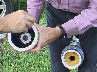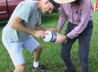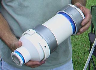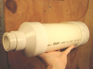
There are four PVC parts to this motor casing. A
section of 4-inch Schedule 40 tube is cut 11 inches long. A cap
is placed on one end, a 4 inch to 2 inch reducer on the other, and a 2
inch to 1-1/4 inch reducer placed in that. These are just the parts, assembled temporarily for photographic purposes. It does not yet have the graphite throat, set in Rock-Ite. It is also missing a ring of PVC that will be placed around the nozzle end which serves as a thrust ring. The first motor had a nozzle made entirely of Rock-Ite. It worked, but eroded quite a bit. So for subsequent tests, Steve turned a nozzle throat of graphite and embedded it in the Rock-Ite. |
Static Test 3
|
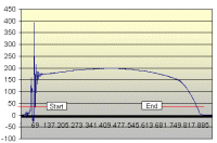
So a third test was called for. On August 7th, we fired it again at my place. This time we splurged and bought a brand-new bottle of PVC cement. Nothing is too good for this motor! Not yet aware that the bath scale had suffered damage, in the 7/9 CATO, we mounted it, turned on all our recording devices and fired. It burned nicely, and the thrust was recorded. After a few scary spikes, the motor settled into a beautiful Bates curve, thrust averaging 176 lbf for 3.28 seconds. Total thrust of 2567 N-seconds places it at the low end of the "L" category, and suggests that it might loft an airframe to some altitude. In the video, one can see the motor shifting slightly as thrust starts. I am convinced that the spikes are artifacts, that the motor was "settling in" to the test stand, causing some bounce. |
Mindful of the incendiary nature of burning metals, but
desperately wanting to see some of the Ti mill chip in this flight, I
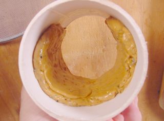
made one grain a Ti delay type. 200g or propellant is mixed with
5g mill flake, and pressed into a crescent in the epoxy-coated
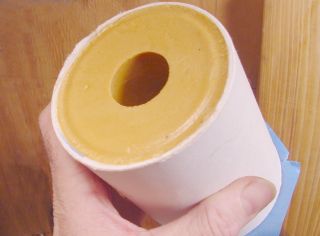
inhibitor tube. Once the propellant is cool and the epoxy hard, I coat the remainder of the tube with more epoxy, place it on my core-centering jig, and pack in more propellant until full. |
Here the assembled
motor, ready for insertion into the airframe. Duct tape is used
in the classic manner to make it fit the airframe tube tightly.
Some small screws will be inserted through the airframe body tube
into the forward PVC cap to ensure motor retention. We don't want
this thing falling on anyone's head from 4800 feet, do we? The ring toward the nozzle is a cut section of PVC coupling, split, and attached with screws. This is the thrust ring, which prevents the motor from moving forward in the airframe. That gap in the ring is fortunate. When we first tried to mount the rocket on the launch rail, the retaining ring got in the way. But we rotated the motor so that the gap aligned with the launch rail, and it fit perfectly. You'da thought it was designed that way. |
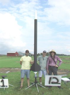
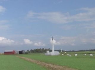
The Flight Launched at NEFAR - Bunnell Blast 10/8/05 Richard Creamer, airframe and electronics Steve Ghioto, motor casing Jimmy Yawn, propellant grains Click Here for 5 meg, 30 second video, .wmv format. |
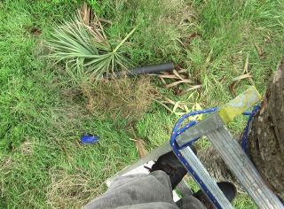
One thing rope is good for is tying the top of the ladder up in the
tree so it doesn't slip off. And for tying myself up in the tree so I
don't have to be competent to stay alive. After some hacking and whacking, the upper section is down along with a few parts of palm. Nose cone is already down on the other side of the tree. Now we can all go home. |